I don’t offer unsoldered kits any more, I sold very few of them and it wasn’t worth the hassle.
There really isn’t much to solder, but I put this quick guide together to help. (Pictures coming soon!)
First of all, a quick one. One of the FLD needs an extra header installed on the output so you can daisy chain the second one to it. Take the three pin header, and place it in the output of one of the boards and solder it in place. I find it easier to have the iron come in from over the LED direction to avoid getting the capacitor on the edge hot and risk losing it. Having said that, it is not critical to the operation so don’t worry if you accidentally desolder it.
Next up is the HPs. You will need to take two of the 30cm extension cables, and one of the 20cm normal cables, and chop off the plug at one end, right next to the connector. On the extensions, keep the socket as you’ll plug a shorter cable into it to give enough reach back to the breakout board. You’ll be left with one HP with a 20cm cable and plug (rear HP), and two with a 30cm cable with a socket. If you trim the red wire down by 5mm or so you’ll find it fits better.
Once you’ve cut the plugs off, separate the wires a little and strip a few mm off the end. You don’t need too much. Twist the ends for easier soldering and tin them. Next I put blobs of solder onto the back of the boards on the three connection points (VCC, GND, Signal). Then, starting at the Signal one, I hold the white wire end against it, and press the soldering iron on. The blob you put there should quickly melt and absorb the wire into it. Don’t hold for too long as the wire will get hot and the insulation start to melt.
Repeat with VCC (red) and GND (black).


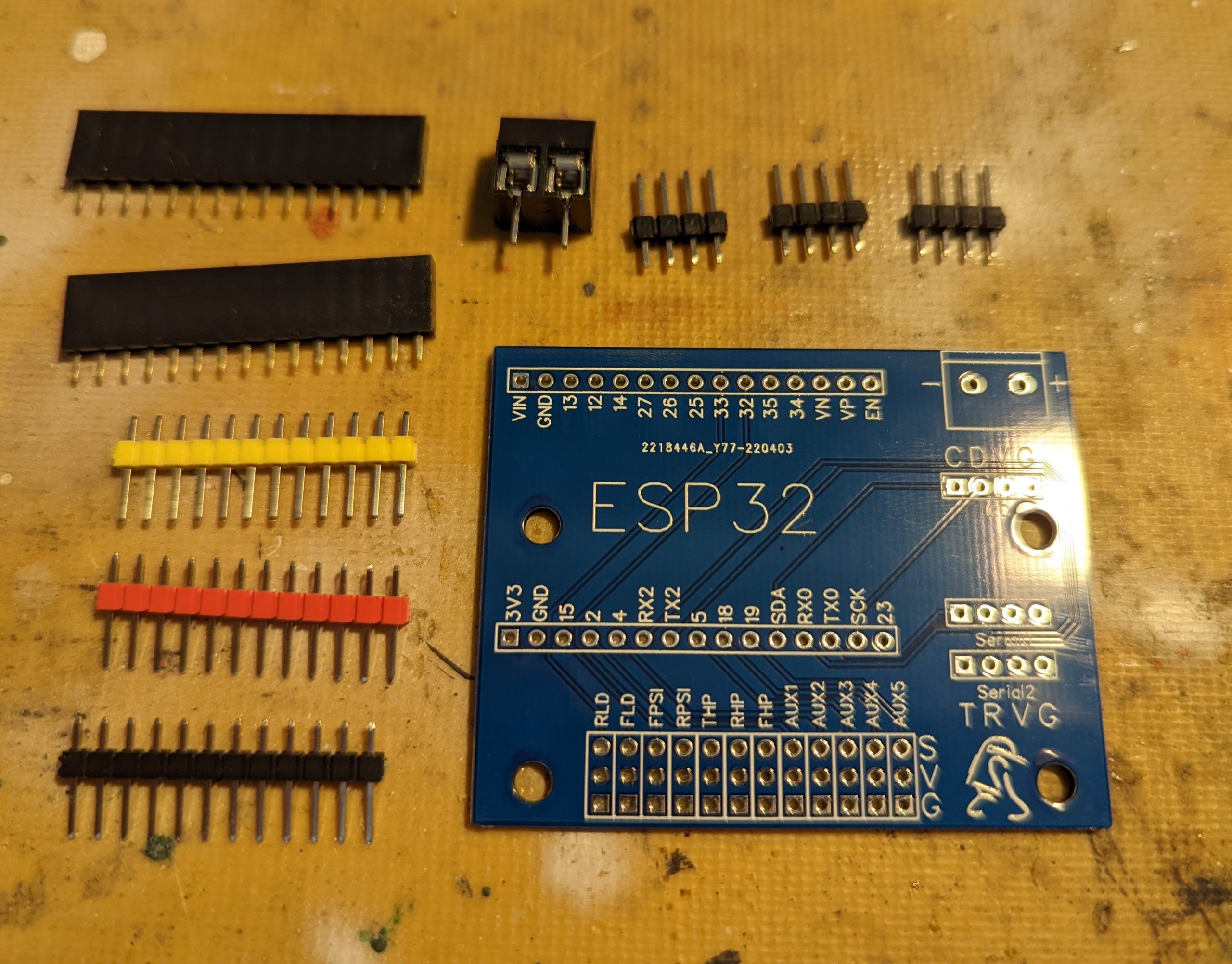
Lastly is the breakout board. Nothing fancy or hard on this, its just a bunch of headers, a couple of sockets, and a screw terminal. I find the best order is to do the long row of headers first, starting with the signal (yellow), then VCC (red) and finally the GND (black). A handy tip is to solder a single pin on the yellow headers, then using one or two of the cut off plugs from the HP cables, you can insert the black and red header pins, and hold them in place with the plug whilst you solder the rest on. This makes sure the pins are lined up perfectly to let you plug all the cables in.
Once these are in I put the three 4-pin headers in for communications, then the two sockets for the ESP32 (Put them on the bottom of the ESP32 to hold them together whilst soldering), and finally the screw terminal for power.


The ESP32 should come pre programmed with the default code, so now you should be able to plug all the boards in and use the usb socket on the ESP32 to do a test.